DA-ODF 960F Fiber Optic Distribution Frame
Dawnergy’s optical distribution frames are designed and
manufactured according to the industry standard. It is used for
terminating and distributing the main optical cable at the central
office, and can easily realize the connection, distribution and
scheduling of optical fiber channels. The main functions of ODF
include: fixing, stripping and protecting optical cables,
terminating optical fibers, scheduling optical fibers, and
protecting and storing optical cable cores, pigtails and jumpers.
Meanwhile, value-added modules such as optical splitter and
wavelength division multiplexer can be installed if required by the
customer. They are widely applied in optical fiber communication
networks and are applicable to central offices and cross-connecting
points in an optical access network.
The MODF Frame design for cable come in CO, with module ODF
splicing, and connect to equipment or other module by Patch cord
cable. Enclosed cabinet structure, sturdy, easy to install or move
optical fibers when needed.
Features
- Full front operation for optical fiber splicing, distribution and
dispatching;
- Supply with R-guide at both side of rack for patch cord in/out and
storage Patch cord. R guide of fiber optic patch cord storage are
located in convenient locations, making it easy to operate and
maintain the system.
- The front is designed with open door type, locked door, allowing
the ODF Module inside to be seen.
- Support bar mounting for Fusion Splicer tray, for test equipment,
synchronously with the rack
- Allows additional installation ODF Module when there is a need to
increase capacity
- When expanding or decrease ODF Module, it is easy operations,
without affecting the other ODF Module being exploited as well as
the connections in use.
- Allows Patch cord and optical cable, in and out to be separated on
both the top and bottom
- Able to protect against dust and insects from penetrating inside
- Back-to-back installation of racks or installation against wall to
save space. Bottom and top of cabinet design the 4 fixed point
support fixed on the floor, Fixed with cable tray ladder.
- Modular design, large capacity, high density, and convenient to
expand Leading optical cables into rack either from the top or the
bottom of a rack;
- Fully-enclosed structure with door, without exposure of fiber patch
cord, pleasant appearance and good dust-proof performance.
- Adapters can be installed in an angle to the front to the cabinet
to prevent laser from hurting your eyes and to facilitate cabling.
- Such value-added modules as optical splitters and attenuators can
be installed, which makes operation and installation convenient and
reliable.
- Operation accessories are also provided, which makes operation and
maintenance convenient and reliable.
- Grounding for all Cabinet
Applications
- FTTH access networks
- Telecommunication networks
Specifications
| Parameters | Specification |
| Maximum Number of Cores | 960 |
| Fusing Splice Unit Capacity | 48 |
| Maximum ODF Module support | 20 Module ODF (each Module high from 1.5 U ÷ 2U) |
| Packing Method | Wooden box packing |
| Material frame and wall | Low carbon steel (mild steel) Powder coated with thickness >70µm electrically insulated from
the inner metal layer Insulation voltage > 34 KV with color is
Light Grey |
| Material of the doors | Make of Acrylic and Bright steel with color APO Grey |
| Radius of curvature of the optical fiber | ≥ 30 mm |
| Cable inlet and outlet | Top or bottom |
| Locking system | Strong lock |
| Loads UDL (heterogeneous distributed) | >300kg |
| Additional UDL load (from top to bottom) | >80kg |
| Dimensions (mm) (H×W×D) | 2200×900×300 Support both type ODF splicing and ODF Distribution with size 19
inch |
Splicing type Operating Principle

1. Cable 5. Fiber patch cord
2. Splicing point 6. Jumper pigtail
3. Fiber distribution pigtail 7. Splicing point
4. Adapter 8. Cable 1
Size and Capacity
| Model | Name | Size(mm) (H×W×D) | Configurable | Remarks |
| DA-ODF-960 | Frame | 2200×900×300 | 1 pc | |
Drawing (mm)


Distribution type Splicing type
Ordering Information
| Model | Name | Description |
| DA-ODF-960-D | Distribution type Fiber Optic Distribution Frame | Distribution type; Telecom grey RAL7035; Max. 960 cores (with
20sets 2U ODF unit); ODF Rack Material: Cold-rolled steel;
Dimensions(mm): 900(W) × 2200(H) × 300(D) |
| DA-ODF-960-S | Splicing type Fiber Optic Distribution Frame | Splicing type; Telecom grey RAL7035; Max. 960 cores (with 20sets 2U
ODF unit); ODF Rack Material: Cold-rolled steel; Dimensions(mm):
900(W) × 2200(H) × 300(D) |
Installation Manual
Content
1. Overview
1.1. Product Usage
1.2. Operating Principle
1.3. Structural Features
1.4. Structure and fiber routing
Size and Capacity
2. Technology Specifications
2.1. Operating conditions
2.2. Insulation resistance
2.3. Withstanding voltage:
3. Installation
3.1 Fixed pieces
3.2 Installation Tools
3.3 Installation and fixation
Drilling
ODF Location
3.4 Installation of frame inner
Application principal DA-ODF-960 series
ODF
Optical Fiber cable entry module of DA-ODF-960
series ODF
Optical fiber cable stripping, fixed and protected
ODF Unit Structure
3.5 Grounding
The high-voltage protection systems
The Protective Grounding
3.6 Rack Combination Installation
4. Operation and maintenance
4.1. Patch cord operation
4.2. Maintenance of Grounding Wires
5. Installation and Adjustment
5.1. Unpacking and Inspection
5.2. Documents, Tools and Instruments
6. Fault Analysis and Troubleshooting
7. Packaging, Transportation and Storage
7.1 Packaging
7.2 Transportation
7.3 Storage
1. Overview
Dawnergy’s DA-ODF optical distribution frames are designed and
manufactured according to the international standard and implement
such functions as the inlet, fixation, and stripping protection for
optical cables, splicing and protection for optical fibers, storage
of pigtail, storage and management of fiber patch cord, fixed
connection and cross connection of optical fibers. Meanwhile,
value-added modules such as optical splitter and wavelength
division multiplexer can be installed if required by the customer.
They can find wide application in optical fiber communication
networks and are applicable to central offices and cross-connecting
points in an optical access network.

- Full front operation for optical fiber splicing, distribution and
dispatching;
- Back-to-back installation of racks or installation against wall to
save space;
- Modular design, large capacity, high density, and convenient to
expand Leading optical cables into rack either from the top or the
bottom of a rack;
- Suitable for ribbon or non-ribbon cables;
- Fully-enclosed structure, without exposure of fiber patch cord,
pleasant appearance and good dust-proof performance.
- Adapter insertion installation, suitable for multiple adapters such
as SC
- adapters can be installed in an angle of 30 degrees to the front to
the cabinet to prevent direct arc light from hurting your eyes and
to facilitate cabling.
- Ribbon cables provide dedicated stripping protection connector to
make the protection of bare fibers and the fixation and grounding
of optical cables more perfect and reliable.
- Such value-added modules as optical splitters and attenuators can
be installed, which makes operation and installation convenient and
reliable.
- Operation accessories are also provided, which makes operation and
maintenance convenient and reliable.
- The 48-core ODF unit 2U with SC/UPC.
1.4. Structure and fiber routing


DA-ODF 960F Splicing type DA-ODF 960F Distribution type
Distribution type Splicing type
| Model | Name | Size(mm) (H×W×D) | Configurable | Remarks |
| DA-ODF-960-D | Frame | 2200×900×300 | 1 pc | Distribution type |
| DA-ODF-960-S | Frame | 2200×900×300 | 1 pc | Splicing type |
| DA-ODU48-SC-D | ODF Unit | 2U×480×260 | 20 pcs | Distribution type |
| DA-ODU48-SC-S | ODF Unit | 2U×480×260 | 20 pcs | Splicing type |
- Operating temperature: indoor type: -5ºC ~ +40ºC.
- Storage temperature: -25ºC ~ +55ºC.
- Relative humidity: 85% (+30ºC).
- Atmospheric pressure: 70 kPa ~ 106 kPa
2.2. Insulation resistance
Insulation resistance between grounding device and cabinet > 2x10⁴MΩ/500V(DC)
Withstanding voltage between grounding device and cabinet no less
than 3000V(DC)/1min, no breakdown, no flying arc.
3.1 Fixed pieces


Figure 3-1 expansion nut Figure 3-2 ligation
It will use electric impact drill, a heavy hammer, socket wrenches
during install and fix the Fiber ODF, As shown in Figure 3-3; And
it will use several kinds of stripping shears, which are shown in
Figure 3-4,3-5,3-6.


Figure 3-3 Wrenches Figure 3-4 stripping shears of fiber


Figure 3-5 stripping shears of sheath Figure 3-6 stripping shears
of fiber
Of course, the professional
fusion splicer will be used except several tools (including wrenches,
screwdrivers).
3.3 Installation and fixation
Drilling in selected location according to the installation sizes
(Figure 3-7, 3-8).
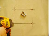
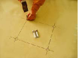
Figure 3-7 Drilling with impact drill Figure 3-8 Heavy hammer nails
expansion bolts
ODF Location
Pushing the ODF to the appropriate location, first take down the
wire slot, then tighten the four screws (figure 3-9and 3-10) with
the wrenches

Figure 3-9 wring screw

Figure 3-10 wring screw with Wrenches wire slot
Application principal DA-ODF-960 series ODF

Figure 3-11 ODF Application
Optical Fiber cable entry mode of DA-ODF-960 series ODF is: cable
into the ODF from upper and lower, as shown in figure 3-12.

Figure 3-12 Wiring pattern of lower into the ODF
Optical fiber cable stripping, fixed and protected
- Introducing the optical cable into the cabinet from the hole which
is above or below the cabinet, and tightened the fiber optic cable
with the fixed sets at the entrance

Figure 3-13 lead the optical cable into the cabinet
- Stripping and fixation of cable

Figure 3-14 Stripping cable
- The cable as an example (as shown in figure 3-15)
- Cleaning the cable;
- Stripping the cable, about 2.5m+the length from the location of
Stripping the cable to the farthest continued module (2.5m+L). An
armor-reserved 40 mm, the central strengthened core for 100 mm;
- Embedding the strengthened core into the fixed-card pieces,
tightening screws;

Figure 3-15 fixed cable
- Stripping and fixation of loose tube optical cable
- Cleaning the cable
- Stripping the cable, about 2.5m+L. the armor-reserved 35 mm, the
central strengthened core 100 mm;

Figure 3-16 Stripping and fix of non-ribbon cable
ODF Unit Structure

Splicing Type ODU

Distribution type ODU, NO splice tray and pigtails
The high-voltage protection systems
The high-voltage protection systems in cabinet is made up of fixed
board, protective device of stripping cable, throat button,
grounding copper line, strength core and armor layer. Fixing the
strengthen core of fiber and armor layer on fixed board with throat
button and protective device of stripping cable, then Series up the
fiber fixed board with wire and the earth lead cross-section is not
less than 35 mm2. Finally, linking to ground copper row with earth lead , the
cross-section of wire is more than 6 mm2
The Protective Grounding
The protective grounding of cabinet is linked from the cabinet’s
top or floor to earth lead copper row, the earth lead cross-section
is not less than 35 mm2.
Note: This grounding belongs to frame of open architecture; the
other semi-closed frames adopt such a grounding mode. Its position
is shown in the location in figure or near the location in figure.
If not clear, please contact me.
- Two grounding must be done, otherwise, my company do not
responsible for any consequences incurred by this.
- We must ground when stripping cable.

Figure 3-18 Army-layer grounding of non-ribbon cable
3.6 Rack Combination Installation
If two or several racks are combined, remove the side panels of
adjacent two racks and connect adjacent columns with bolts. If
cables are led into the DA-ODF-960 from the bottom of the rack, it
is necessary to lead the cables to the switching position of the
inlet box and the lower two termination units
4. Operation and maintenance
4.1. Patch cord operation
1. Select Φ2 mm or Φ3 mm patch cord. As shown in Figure 4-1;
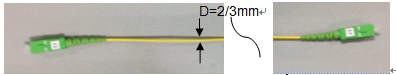
Figure 4-1 Select patch cord
Insert one end of patch cord into adapter; insert the other end to
corresponding adaptor after coiling of ring.
2. It may be connected directly or cross-connect.
3. Repeat steps 2, 3 to complete the patch cord operation, finally
marking the finished patch cord record (Figure 4-2).

4-2 Log of patch cord identifier
4.2. Maintenance of Grounding Wires
Check and tighten individual connection points, with emphasis on
short circuit caused by contact of metallic conductors. Make
maintenance record and statistics of exceptions.
5. Installation and Adjustment
Precautions for installation and contents for personal and
equipment safety shall be highlighted and marked with Caution or
Danger symbol (as shown in the figures blow) or indicated with
warning statement. Precautions for operation shall also be
indicated. Add some novel pictures or red marks if necessary.
 Note
Note  Danger
Requirement for floor: Concrete floor with intensity not less than
27.4 Mpa
5.1. Unpacking and Inspection
Check all components one by one against the name, specification and
quantity in the packing list.
5.2. Documents, Tools and Instruments
| SerialNo. | Category | ToolName |
| 1 | Installation tool | Wrench, sleeve, screwdriver |
| 2 | Documents | Technical Description of DA-ODF-960-D Optical Distribution Frame |
| 3 | Documents | Technical Description of DA-ODF-960-S Optical Splicing Frame |
6. Fault Analysis and Troubleshooting
| Serial | Common Fault | Cause Analysis | Troubleshooting and | Remarks |
| 1 | Disconnection of transmission line or poor transmission effect | Inappropriate bending radius causes permanent physical deformation
to the optical cable/fiber and increases transmission loss | During construction, the engineering personnel must pay attention
to the protection of bending radius of fibers (bends and
bottlenecks for cable inlet and outlet in racks) and ensure that
the cable routing is reasonable | |
| Loose connection, great loss of optical fiber active connectors
(adapters, pigtails/fiber patch cord) | Check whether all threaded or plug-in mechanical connectors are
firm and meet their respective standards | |
| 2 | Optical fibers are easy to fall off or not reliable | The most fragile part of the optical fiber/cable lies in the
position where abrupt physical structure change happens, which may
affect the security and reliability of the entire network | Be careful in cable fixing, stripping protection, secure grounding,
and splicing point protection; no error or omission is allowed.
| |
| 3 | Redundant fiber storage disorder | Caused by insufficient cable length in design or careless work of
construction personnel | Sufficient fiber core shall be reserved during product planning.
Adjust cables during construction to make cables in the rack clear
and neat. | |
| 4 | Unclear labels | Disorder caused by the dismantle during construction or maintenance | Clear labeling and detailed records | |
7. Packaging, Transportation and Storage
7.1 Packaging
In DA-ODF-960 series of products, cabinets and racks are packed in
cartons. Products (including accessories) are packed according to
packaging specifications and are damp-proof and shock proof .
Accessories and spare parts are placed into respective bags and
then placed in the packing box. The integrated equipment is sealed
with a plastic bag. Rainproof, moisture-proof and direction marks
are provided on the outside of the packing box.
7.2 Transportation
After being packed in wooden boxes/cartons, DA-ODF-960 products can
be transported by motor vehicle, train, ship, or airplane. Prevent
the products from collision, falling, rain, snow and direct
sunshine during transportation.
7.3 Storage
The DA-ODF-960 products should be stored in a dry and ventilated
warehouse without any erosive gases. The storage temperature should
be -25ºC ~ +55ºC.


